

Introduction
To address the lack of accessibility to synthetic biology due to the high costs and the level of knowledge required among others, our team has designed Printeria, a fully-equipped bioengineering device capable of automate the process of printing genetic circuits in bacteria.
To ensure a functional, economical and easy-to-use design, collaboration between the hardware and the wet lab teams has been necessary throughout the development process. After several drafts we have achieved a unique design that can be easily transported and replicated at a cost not exceeding 1.030,02 € (1.192,92 $).
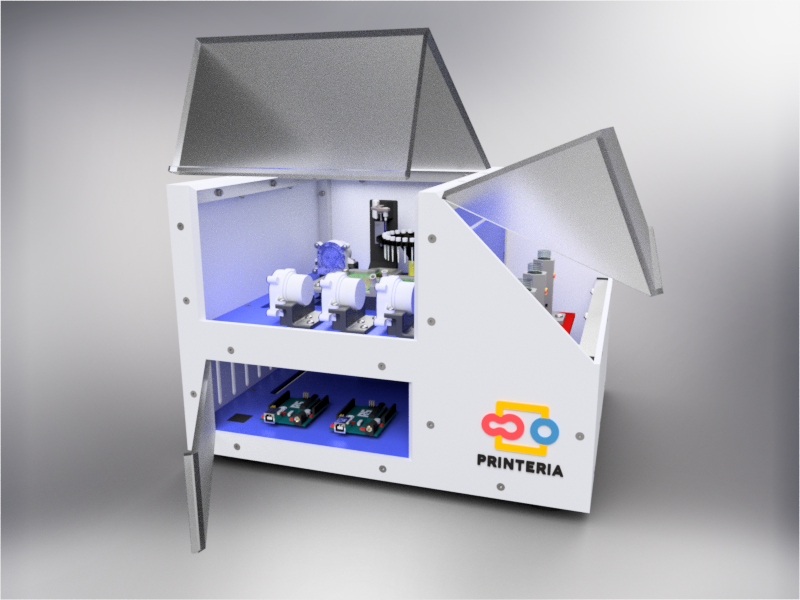
Image 1. Printeria
Printeria is divided into three main parts dependent on each other:
-
Entry of consumables: components that allow the entry of consumables into the reaction zone.
-
Reaction zone: space where the process of printing genetic circuits in bacteria occurs thanks to digital microfluidic technology.
-
Measurement zone: the bacteria are kept in conditions that allow for growth and expression while OD and fluorescence measurements are taken.

Image 2. Assembly Sketch
The software team has developed an intuitive software that controls the operation of Printeria and allows the user to easily design the genetic circuit that is going to be printed.
-
Overall budget
Part Quantity Cost per unit Cost Structure 1 381,91 € 381,91 € Entry system 1 49,02 € 49,02 € Reaction zone 1 484,99 € 484,99 € Measurement zone 1 114,10 € 114,10 € Total 1.030,02 € -
Downloads
Frame
First of all, it is necessary to design a structure that confines all the elements necessary for the operation of the device inside it and also allows the creation of a sterile atmosphere to carry out the biological reactions.
In order to facilitate its transport, aluminum has been chosen for the frame, which in addition to its low weight, has other great qualities such as great resistance to corrosion and low cost.
It has been used 15x15x1mm square tube profiles joined by plastic corner connectors obtaining as a result a 415x360x280mm chassis. Thanks to the generated blueprints we have been able to contact a company specializing in cutting and handling aluminum that has provided us with all the parts as we required. As it was not possible for us to find plastic connectors that fit our needs, we have decided to design these parts ourselves and then print them on a 3D printer.
Image 3. Aluminium frame
Methacrylate
To complete the structure, it is necessary to create walls that are attached to this frame and contribute to its stability. We have opted for the use of methacrylate due to its attractive appearance, durability and scratch resistance.
During the process of designing the device several sketches were made and after consulting potential users of the machine it was concluded that the front lid of the device should be as large as possible to facilitate the feeding of consumables. In addition, it has been decided that this lid should be transparent in order to allow the user to observe the reaction if desired, thus being able to detect possible failures at a glance.
On the other hand, the right lid that covers the output system is transparent to show what is inside but it should be completely opaque to prevent the entry of light and thus obtain better measurements of OD and Fluorescence.
As well as the aluminum profiles, the blueprints created were used for ordering the custom-made parts to a company.

Image 4. Methacrylate cladding
Finally, 4mm diameter countersunk head screws DIN 7991 (M4 L25) and nuts DIN 934 (M4), both made of galvanized steel, were used for joining the methacrylate plates to the frame.
Thanks to the use of plastic connectors and bolted joints, the entire structure can be disassembled and reassembled as often as required, making it much easier to transport and store.

Image 5. Parts of the structure before assembling
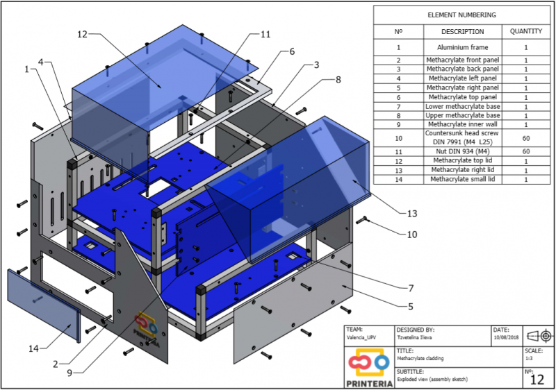
Image 6. Assembly sketch of the methacrylate cladding
Leveling system
Given the great importance of keeping the reaction zone perfectly horizontal, it is necessary to use levelling feet. In addition, for checking the horizontal position, a bull’s eye level has been installed next to the reaction zone.

Image 7. Leveling system
-
Structure's budget
Part Quantity Cost per unit Cost Aluminum profiles 6 m 6,99 €/m 41,94 € Profiles' cutting and drilling 1 70 € 70 € Custom-made methacrylate 1 250 € 250 € Screws DIN 7991 60 0,07 € 4,2 € Nuts DIN 934 60 0,03 € 1,8 € Kg of PLA for the connectors 0,155 Kg 20 €/Kg 3,1 € Leeveling feet 4 0,97 € 3,88 € Bull's eye level 1 6,99 € 6,99 € Total 381,91 € -
Downloads
In order to carry out the reactions it is necessary to introduce the consumables into the PCB. Therefore, a carousel-based system has been designed in which pipette tips with the parts necessary for the reaction are placed. The user should place these pipette tips before the experiments on the positions indicated.
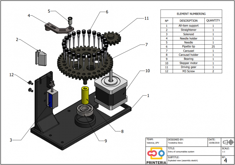
Image 8. Entry system assembly sketch
Once the tips have been inserted and the machine is ready to operate, the carousel is rotated with the help of a stepper motor until each of the tips is placed in the blowing position. In this position a needle connected to a peristaltic pump lowers vertically and injects air, thus producing the fall of the genetic material on the PCB.
The vertically moving needle was made possible thanks to the use of a solenoid, a device that converts electrical energy into mechanical energy which, in turns, raises or lowers the needle. Once the needle is on its low position and inserted into the pipette tip, the pump is activated and air is injected.

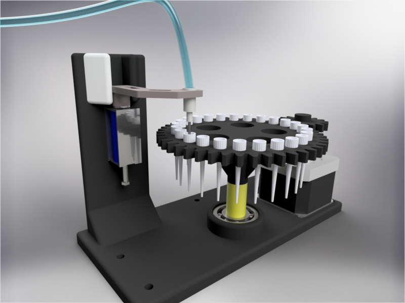
Image 9. Needle on its high and low position
All the necessary parts have been designed using a 3D modeling software and then printed on our 3D printer, which means that we have been able to implement this system at a very low cost.
Image 10. Proof of concept of the entry system
-
Entry of consumables system's budget
Part Quantity Cost per unit Cost Kg of PLA for the 3D printed elements 0,115 Kg 20 €/Kg 2,3 € Bearing 1 2 € 2 € Needle 1 0,3 € 0,3 € Stepper motor 1 26,43 € 26,43 € Solenoid 1 5 € 5 € Peristaltic pump 1 11,99 € 11,99 € Air filter 1 1 € 1 € Total 49,02 € -
Downloads
Digital Microfluidics Movement
For the main part of the device we needed to be able to reliably and precisely control the movement of the liquids involved in the reaction. This ensures that the components mix was intended and then follow every procedure accurately. For this we have decided to use a technology called digital microfluidics (DMF), which is based on applying electromagnetic fields to a special surface so that it changes its properties. More precisely we can change the hydrophobicity of the surface as to attract droplets and repel them, ensuring in this way that they follow an established route.
This enables us to mix the different components, split the mixture into separate droplets to control the volume and allows multiple reactions to take place in very little space thanks to this flexible technology.

Image 11. DMF technology
To take advantage of this we have designed the PCB under the surface with small pads on which we can apply a high voltage to cause this effect on the coating of our surface.
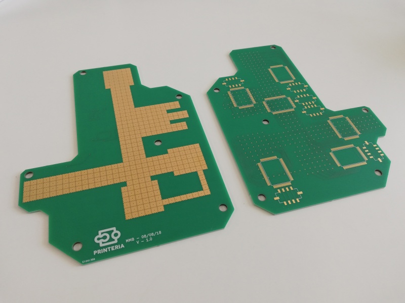
Image 12. PCB designed
This surface must be very hydrophobic, therefore it is necessary to coat the PCB with a polytetrafluoroethylene (PTFE) foil (12 microns thickness) and then apply a thin layer of a very hydrophobic gel called FluoroPel. In order to keep the Teflon foil well glued to the surface of the PCB, a custom-made piece has been designed and printed. The foil will be glued to this piece and then joined to the PCB by means of screws.
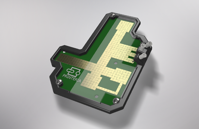
Image 13. PCB designed and its holder
To be able to control so many pads we are using a HV507, a special driver chip which is a high voltage serial to parallel converter. This means that it takes data one bit at a time and then it displays them all at the same time at a high voltage. This chip can handle up to 64 outputs, meaning that we can connect 64 pads to it. So we only need a total of 6 chips for our entire surface.

Image 14. Driver chips on the PCB

Image 15. Proof of concept of moving droplets
To get the droplets out of the reaction surface we have designed a holder for a syringe that has a tube with a pump connected to the experiment zone and the output recipient. For extracting the droplet we move it to the syringe tip on the PCB surface and then activate the pump. This absorbs the droplet, makes it pass between 2 metal plates that electroporate it, and drops it on the output tube. This part of the device is also used for dispensing later the 3 ml of LB medium onto the tube. In addition, it is also used for getting the cleaning droplets out of the experimentation zone, while cleaning the tube itself.
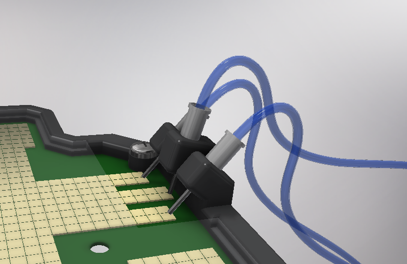
Image 16. PCB output
ThermoCycling by displacement of droplets
For the Golden Gate assembly reaction we needed to make the droplets with the DNA and the enzymes go through a thermocycling process, which means to change the temperature in cycles.
| Time | Temperature | Number of cycles |
|---|---|---|
| 10 min | 37 ºC | 1 |
| 3 min | 37 ºC | 25 |
| 4 min | 16 ºC | |
| 10 min | 50 ºC | 1 |
Table 1. Thermocycling process
To take advantage of the digital microfluidics, instead of changing the temperature of a fixed place, we have decided to have the droplet alternating between two places that are at the correct temperature. This means that the temperature of the droplet changes very quickly. And it also means that we only have to stabilize two discrete temperatures instead of changing them constantly, which translates into greater temperature accuracy.

Image 17. Hot and cold zones on the PCB and thermal image
-
For the hot zone we use a power resistor attached to the PCB from below and to control the current going through it we use PWM. This means putting shortly quickly alternating between voltage on or off to create a pseudo analog voltage that is a percentage of the applied voltage depending on the duty cycle. If the pulse is longer the analog voltage would be closer to the real voltage.
-
For the cold zone a Peltier effect device is being used. This effect consists of directly converting a difference in voltage into a difference in temperature due to the P and N semiconductors that, when carrying current, transfer the heat from one side to the other.
This means that we have to get rid of the heat generated so we can keep the temperature difference that the peltiers produce. For that reason, we have implemented a stock liquid cooling solution from a computer that works by a liquid flowing constantly between the peltiers and a radiator, effectively dissipating the heat.

Image 18. Liquid cooling device
For having a good precision and better efficiency we use voltage control. Which means actually changing the DC voltage level to alter the temperature difference. With peltier effect devices PWM is not a suitable control method because they require constant current to properly function.


Image 19. Resistance (left) and Peltier (right)
At both zones we are going to keep a thermistor monitoring the temperature to complete the control feedback loop. This thermistor is calibrated by using a lab grade thermometer and then adjusted using Steinhart-Hart model coefficients based on the readings. This means that we took readings on liquids with known temperatures and then read the raw resistor data. Based on those readings we can obtain the coefficients for our resistor-temperature curve and convert the voltage of a tension divider measured with our arduino into a really accurate temperature reading.
Output electroporation
We have chosen to do the transformation of the cells in Printeria by electroporation. The cells will enter Printeria via the entry carrousel in a pipette tip stored at -20ºC. We found that at this temperature the competent cells were transformed with sufficient efficiency for at least the first two weeks.
From this point on until the assembly reaction is complete, the competent cells are transported to a zone at 4ºC where they will remain stored. Once the assembly is complete the competent cells are mixed with the assembled genetic material and transported to the electroporator.
The reason for choosing electroporation as a transformation method is that, as we have seen, it is the most efficient method outperforming heat shock and other commercial methods. Furthermore, for the implementation of the electroporator in Printeria we have used the design developed by the Valencia_UPV team in 2016 for the HYPE-IT project, modifying its electronic circuit and designing a new PCB.
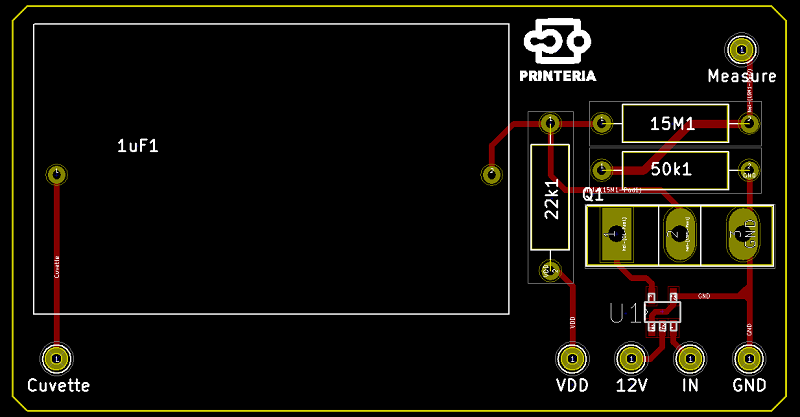
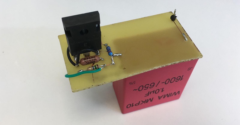
Image 20. Electroporator
The electroporator is situated on the tube that transports the droplet with the DNA and bacteria to the measurement zone. The circuit charges a Capacitor at 1600V with step-up converters and then a simple circuit with a transistor is able to apply the voltage to the two metal plates placed on the transporting tube. This means that we can apply a voltage during a very short period of time, producing the required reaction.
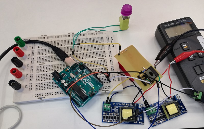

Image 21. Electroporator proof of concept
-
Reaction zone's budget
Part Quantity Cost per unit Cost PCB Surface 242,11 € PCB 1 81,97 € 81,97 € Chip HV507 6 12 € 72 € FluoroPel 25gr. 86,14 €/25gr. 86,14 € PTFE sheet 1 2 € 2 € PCB Thermocycling components 112,11 € Peltier 30W 2 25,35 € 50,70 € Resistencia 10ohm 25W 1 4,91 € 4,91 € Refrigerator 1 56,50 € 56,50 € Electroporator 8,78 € Capacitor 1uF 1600V 1 5,68 € 5,68 € MOSFET Driver 1 0,54 € 0,54 € Capacitor 470pF 100V 2 0,39 € 0,78 € Resistors 22K 15M 50K 5 0,35 € 1,78 € Control Logic 40,20 € Arduino 2 16 € 32 € HUF76423P3 mosfet 10 0,82 € 8,20 € Power supply 56,90 € 100W External Power supply 1 21,95 € 21,95 € 5V-750V DC/DC Converter 3 8,32 € 24,96 € 12V 8A stepdown Converter 1 9,99 € 9,99 € Disinfection and sterility 13,99 € UV light 1 13,99 € 13,99 € Sensors 10,90 € Thermistor 2 5,45 € 10,90 € Total 484,99 € -
Downloads
Also known as the output system, the measurement zone consists of an area separated from the rest of the zones in which the ideal conditions for the growth of bacteria are established. These conditions are achieved thanks to an electrical resistance that maintains the temperature of the whole zone at 37º and a shaker that keeps the test tubes moving to achieve a homogeneous mixture. In addition, sensors for OD and fluorescence measurement have been implemented to monitor the entire process.
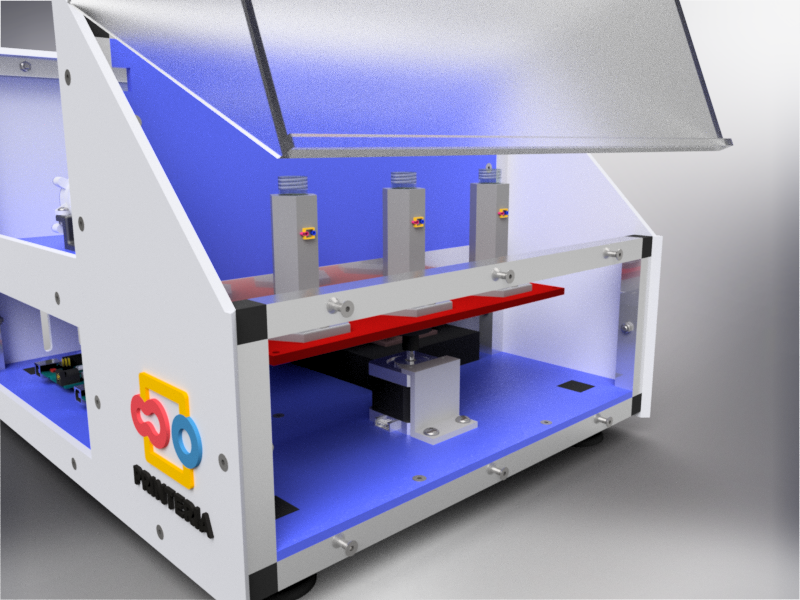
Image 22. Output system 3D model
The shaker is achieved through the use of a stepper motor connected to a methacrylate base by means of an eccentric piece and a bearing. This eccentric piece produces the oscillating movement of the methacrylate base with the help of a spring that limits the rotating movement.
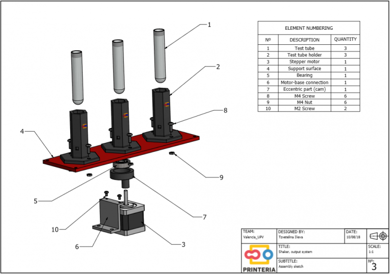
Image 23. Exploded view of the output system
To this methacrylate base will be attached the test tubes’ holders in which the bacteria are contained and to which the sensors will be connected to take the measurements of OD and Fluorescence during the whole cycle of growth of the bacteria.
Both the eccentric piece and the test tubes’ holders have been designed by the team and obtained thanks to our 3D printer using PLA filament.

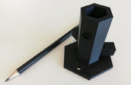
Image 24. Eccentric piece and test tube's holder
How does it work?
Before putting the machine into operation, the user must insert a 14 ml tube with 700ul of SOC (antibiotic-free recovery medium) into the output. Once the reactions have taken place in the experimentation area, the genetically modified and electroporated bacteria will be introduced into the 14ml tubes by means of peristaltic pumps where they will remain for 1 hour being shaken.
Subsequently, by means of the peristaltic pump, 3 ml of LB medium are introduced with the antibiotic to complete the bacterium growth cycle and after 16 hours the bacteria are ready and the user can remove them.
It should be noted that although the number of bacteria transformed with plasmids without the correct assembly has been significantly reduced, the culture obtained will not be pure. In order to obtain a pure culture it would be necessary to always make a step by plate of the culture and to isolate a transformed colony with the correct assembly.
Sensors
-
OD: As for measuring the resulting bacteria we need a high precision light sensor we decided to use TSL235-LF. This converts the magnitude of light received into frequency, which can be precisely measured. Our sensor compares the light from a laser of 650 nm that passes through the experimentation tube over time. We chose a laser for a more stable light output. Comparing the values measured to the initial values without any bacteria we can calculate the percentage of absorbance of the medium, obtaining that way a suitable measurement of the cell population.
For the implementation of this sensor we took advantage of the design developed by the Valencia_UPV team in 2016 for the HYPE-IT project but we have enhanced the software that controls the OD meter.
-
Fluorescence: Similarly to our OD sensor we opted for the TSL235-LF for high precision light measuring. The only difference is that in this case the bacteria are excited with a LED of wavelength 480 nm, since it is the most suitable to excite them and obtain a fluorescent reaction from them. In front of the sensor we have put a filter that only allows light of 511 nm of wavelength to pass through. That way we obtain a result on the peak of fluorescent emission from the bacteria.
We have calibrated the data from the OD and Fl sensors with the OD and fluorescence data from the Biotek Cytation3 equipment obtaining both calibration curves.

Image 25. Shaker proof of concept
-
Measurement zone's budget
Part Quantity Cost per unit Cost Kg of PLA for the 3D printed components 0,160 Kg 20 €/Kg 3 € Methacrylate plate 1 5 € 5 € Bearing 1 2 € 2 € Stepper motor 1 26,43 € 26,43 € Peristaltic pump 3 11,99 € 35,97 € TSL235-LF sensor 6 3,10 € 18,60 € Led 480 nm 3 0,20 € 0,60 € Láser-Red 650 nm 3 7,50 € 22,50 € Total 114,10 € -
Downloads
It is really important to keep a sterile atmosphere around the reaction. To ensure this we have implemented a series of measures to keep Printeria clean:
-
UltraViolet light: We have installed UV leds under the aluminum profiles in order to sterilize the reaction surface between uses. In order to achieve disinfection, the short wavelength of ultraviolet light is required to be between 280 and 100 nm.
-
An air filter with a 220 nm pore size on the peristaltic pump of the entrance.
-
Filtered ventilation holes.
-
Water and alcohol or HCl droplets that sweep across the surface in order to absorb any remaining of the reaction.
The disinfection process involves that once the test tube with the genetically modified bacteria has been removed, the user must place an empty tube in the exit position.
After that, by means of the entry system, drops of water and HCl or alcohol will be introduced. These drops will go through all the pads to sweep all the genetic material that may have adhered to the surface and then will go to the extraction area of the PCB. Once there, they will be absorbed by the peristaltic pump and after going through the whole tube and cleaning it, they will fall into the test tube placed at the outlet. This tube will be removed by the user and placed in a autoclave bag for biological waste.
Finally, after cleaning the surface, the UV leds will be activated and it will be completely disinfected and sterilized for a new use.
One of the possible upgrades that we would do to Printeria for better usage in the future is the parallelization of experiments. This means being able to run multiple experiments at the same time in paralel. We support up to three reactions at the moment but we are limited by the design of the output zone and the input of the machine. We could alter this design to be able to do many more reactions at the same time, or one right after another to optimize the resources inside the machine.
In addition, one of the great advantages of Printeria is that the Output system can be independent from the rest. In this way, it is possible to introduce any culture of bacteria that has not been created in the machine to monitor its growth. Through the software, in a independent tab, it will be possible to only make measurements. The user will decide which measurements to make (OD, fluorescence...), and the results will be shown and stored in his library of measurements, which could be accessed at any time.